Loopy Pro: Create music, your way.
What is Loopy Pro? — Loopy Pro is a powerful, flexible, and intuitive live looper, sampler, clip launcher and DAW for iPhone and iPad. At its core, it allows you to record and layer sounds in real-time to create complex musical arrangements. But it doesn’t stop there—Loopy Pro offers advanced tools to customize your workflow, build dynamic performance setups, and create a seamless connection between instruments, effects, and external gear.
Use it for live looping, sequencing, arranging, mixing, and much more. Whether you're a live performer, a producer, or just experimenting with sound, Loopy Pro helps you take control of your creative process.
Download on the App StoreLoopy Pro is your all-in-one musical toolkit. Try it for free today.
Comments
I’m surprised nobody’s invented the vernier slider
Metal work complete. 1mm thick steel plate. Took quite a bit of work.
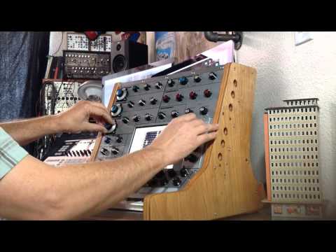
Awesome. I wish I had the patience and skills to even attempt building a controller. Good luck.
I think this is the same guy who made the epic Animoog controller.
https://www.synthtopia.com/content/2014/03/29/the-ivcs-controller/
I'm just learning as I go.
Inkjet printed transparent film applied to metal work.
Wondering if I should have gone for white background. Hmmm 🤔
Looks lovely 🙌
Pots fitted. Starting to look like a controller.
Thank you,
for your good information, and lots of love.[SIZE=1][URL="https://gbplus.net/download-gbwhatsapp-apk/"][COLOR="#FFFFFF"]g b whatsapp download[/COLOR][/url][/SIZE]
Thank you,
for your good information, gb whatsapp
and lots of love.
The tedious joy of soldering
More soldering.
So is it a giant voltage divider in principle? I’ve never looked into how these things work…
Basically yes. There are 3 pins on each potentiometer which act as a voltage divider. All the red wires are joined together and so are all the black wires. The left one (red wires) goes to + voltage, the right one (black wires) goes to ground and the middle leg will go to the input of the microcontroller that has an analogue to digital converter.
I've not attached the middle leg wires yet. That will be tomorrow night as it takes me quite a while but once that's done then that's the majority of the soldering done.
Ah, I see, that makes sense 👍
More soldering. Nearly done on the main wiring.
What a work , music and DIY
Thanks BerlinFx
Only just clocked this… that is some nice, clean drilling. Skills!
I just did this (16 x 9mm holes into copper pipe x 2)… what a pita!

Nice work Kewe_Esse. What is it?
It’s lighting for a market stall/pop-up shop. Builds into a bigger structure for displaying signage/clothing/other stuff… part of an ongoing project. Bit off-topic, hands up, but I feel you on the drilling, surprising amount of work involved.